Pages

Sunday, February 20, 2011

almost

How many times have I said "almost"? I've lost count. I think I've been saying "I'll be ready to brew my first test batch in about 2 months" for the last year now. Well, this time "almost" is taking on a new meaning because I'm really almost there. There's some electrical wiring connections to be made, immersion chillers and internal kettle arms to be formed, and tests on the controller programming. And then, it'll really be ready!!! And you better believe I've got my fingers crossed that it'll all work as hoped!!!


mash tun false bottom modifications

What's the first thing you do when you get your shiny new Blichmann Boilermakers? If you're like me, you start cutting new holes and welding things onto it. But most of my friends will tell you that you shouldn't be like me, so do this at your own risk. In my last post, I explained how I modified some rotating racking arms from St. Pats for the kettle main ports and return ports. Pictured below is the new mash tun pick up tube and how I handled modifying the Blichmann false bottom to accommodate the new pick up tube.  I added additional pictures of the false bottom work in the Bluto 555 kettles gallery, as well as some additional pics of work on the kettles.


The hole pictured above is plenty big enough to allow inserting and removing the pick up tube.  A couple of additional stainless washers are used to slide over the pick up tube before adjusting it into place, and then you slide them back down to rest on top of the welded-on washers, in order to prevent grain from flowing through around the pick up tube during recirculation.

main port and return port fittings

I've added some pics to the fittings gallery to show how I'm coming through the kettle wall at the main port and the return port. Originally, I thought I'd have a TC ferrule on both the inside and outside of the kettle at the main and return ports (similar to the way Stout Tanks and Kettles has designed their mash tun return port), but welding a TC ferrule into the inside of the kettle down near the bottom for the main port proved to be too difficult.  It took me a while to figure out another way, and I eventually settled on modifying some rotating racking arms from St. Pats. Unfortunately, it's just about impossible to link to specific pages on St. Pats's website, so you have to click on Rotating Arms in the left column and then scroll down about 2/3 of the way down (or I took some screen shots and uploaded them here and here).

For the mash tun main port pick up tube (not pictured below), I left the horizontal part of the tube (for lack of a better way to describe it) alone and simply cut off the vertical part so it could point straight down inside the kettle.  For the boil kettle main port dip tube (pictured below), I shortened both the horizontal part of the tube and the vertical part. The ability to rotate this pick up tube from the outside of the kettle should (if necessary if I don't get a good trub cone following the whirlpool) enable avoiding picking up junk off the bottom of the kettle.

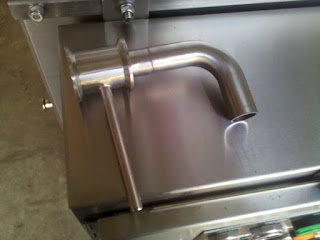
boil kettle dip tube
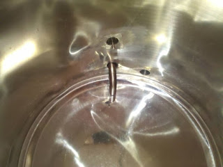
I used the same St. Pats racking arms for the return port, except for these I basically cut off all but an inch or so of the arm and welded on a reducing tube stem fitting from McMaster-Carr (which was also slightly modified).  The pics below show how this is designed to work so that you can basically create any type of internal kettle fitting you want to attach to the inside of the return port (mash wort return, sparge arm, whirlpool wort return, etc.) The pumps used on the system have a 1/2" exit, and the tubing from the pump to the return port is 1/2" ID. The tube stem fittings allow for a 1/2" OD tube, and a stainless 1/2" OD tube has an ID of .46", so there's not too much further restriction coming in through the return port like this when using the stainless tubing.  With 1/2" OD copper tubing, the ID is 3/8" but I only plan to use copper tubing internally for sparging and mash wort return, so hopefully that additional restriction won't be a big deal.

return port fitting idea
return port fitting
return port fitting

idea for motorized mash mixer

Here's a few pics of the idea I have for a motorized mash mixer. I haven't started on this yet, but it's something I really want to add to the system at some point. It'll be an expensive addition, so it's something I don't care to screw up. I've made a few design mistakes on the system so far, but nothing that I haven't been able to solve or tolerate (I hope!). Alot of contemplation is in order before I move forward with this part. I'm really eager to test a few typical batches before getting into decoction mashing anyway.

The idea is to create an addition to the frame (that can be bolted on when needed and removed when not needed) on which can be mounted a gear driven motorized mixer. The picture below shows an example of such a mixer, although I'd need blades of a larger diameter. The motor would need to be variable speed and capable of around 35 rpms (at least, my understanding at this point is that the blade shouldn't turn faster than 35 rpms). Some of these electric gear driven motors have an rpm range of 0-350 rpms. I'll just need to figure out how much horsepower is needed to stir a typical mash for the size batch appropriate for this system. Theoretically, with 5 kettles, you could split a mash up into 3 parts, stepping up the temperature of each as necessary and then continuing with the mash that has the mixer to bring it up to a boil for a while.

Special thanks to Donald Put, who wrote an article years ago on motorized mash mixing for Brewing Techniques magazine.


I created a new gallery for work on the motorized mash mixer here. For now, there are only a few more pictures of the drawing in the gallery, but I hope to add more later when the work on it is actually being done.

Sunday, February 6, 2011

1 bbl (40 gallon) conical fermenter and freezer conversion

Here's some pics of a 1 bbl conical fermenter from Stout Tanks and Kettles (40 gallons total capacity) and the conversion of a 20.5 cf upright freezer from Lowe's. Stout has a diagram of how this conical fits inside the freezer here.  I really don't see the need for the 3/4" plywood on the floor yet.  I'm a big guy, and I got inside the freezer and stood on my heels and toes in every spot I could, and the floor never seemed to be affected.  I think it'll be ok without.  I hope to put this fermenter to the test very soon.

click for more pictures
Priscilla and I spent about 3 or 4 hours total converting the freezer to hold the fermenter.  We unscrewed all the screws on the outside of the door panel and removed it.  The gasket comes off with the panel. We decided to glue the gasket back in place, and this was a pain, especially since we did it without taking the whole door off the freezer first.  We tried using clamps to hold it in place, which didn't work well, so we ended up carefully taping it in place and letting it dry until the next day.  The glue held well, but we ended up deciding that we really didn't need to glue the gasket on to begin with. You can just as easily cut around the outside edge of the door panel, so that you end up with an approximately 1" strip of door panel just to make use of the screw holes.  Using this will hold the gasket in place just fine.  Next, we glued a piece of 3/4" insulation board to the inside of the door and put cold weather aluminum tape across, from top to bottom.

The freezer and a heat belt designed for a 30 gallon drum are both plugged into a Ranco 2-stage temperature controller, and the temperature probe from the Ranco is plugged into a sanitary thermowell from GW Kent. In case you're looking at this and thinking about a similar setup, you might want to consider a less powerful heat belt. I haven't put this to the test yet, but I suspect the heat belt pictured needs to be seriously downgraded.  More on that later after I'm able to test it out.

Friday, February 4, 2011

the gas manifold

The gas manifold is finally complete. I added a few pics to the Bluto 555 combustion gallery.  I sized the main line at 1-1/4" to facilitate potentially all five burners operating at full blast simultaneously.

Using the propane burners I have (175k btu/hour each), that would require the main manifold (which is just over 10 feet long) and supply line to be able to handle up to 875k btus/hour).  Consulting the engineering toolbox, I can have a run of up to 40' of 1-1/4" pipe and still have a capacity of 900k btus/hour. Alternatively, if I'm using my natural gas burners (160k btu/hour each), theoretically all at the same time for a total of 800k btus/hour, the engineering toolbox natural gas piping chart says I can have up to 20' of 1-1/4" pipe for a capacity of up to 850k btus/hour.

click for more pictures
3/4" pipe is used for each of the individual burners, which is more than enough capacity for either 160k or 175k btus/hour.  I'm also using 12" Dormont flexible gas connectors (DOR-1675BPCF2S12) with swivels, shut-off valves and quick disconnects, which each have a capacity of 230k btus/hour.  The Dormont connectors are used in commercial kitchens to facilitate rolling equipment away from walls to clean, without having to disconnect the gas line.  They're made to withstand repeated stress and are covered with an anti-microbial pvc coating. They're expensive, but (as far as I know) they're the only gas connectors approved for repetitive flexing in a commercial environment.  The Dormont connectors allow me to easily lower and raise the burners as needed, anytime.