Pages

Tuesday, December 28, 2010

work on the Satellite Enclosures

I added some pics to the Bluto 555 Electrical gallery to show some work done on the Satellite Enclosures, which are 16 gauge stainless steel, so I had some learnin' to do. Each Enclosure needed 6 holes cut: one 1/2", three 30mm, and two smaller (I forget what the small size was now).

The best way to do this on the larger holes is with knockout punches. Be careful, knockout punches can be really expensive for uncommon sizes, such as 30mm, but they make a very clean cut. Here's a link to a youtube video I watched to learn more about knockout punches before I cut my first hole.

A couple of lessons learned about drilling and cutting stainless:

(1) slow and steady with a good amount of force pressing on the stainless is best. If you start thinking you have to speed up the drill a bunch to make progress, you're probably going to end up going too fast, which easily makes the affected spot too hot and actually makes it harder to drill. Remaining at a slow speed and increasing the pressure applied works best. How many rpms is best? I'm not sure, but I kindof got the feel for it within a few holes.

(2) Use machine oil where you're cutting, both for drilling and using the knockout punches.

(3) For drilling (even when using the knockout punches, you have to drill a smaller hole first), use a drill press if you have access to one and it will work for the spot you're drilling. Drill presses can be set to a slow rpm, and it is really easy to apply consistent pressure. My neighbor insisted I use his drill press when he saw me using a hand drill, and using the drill press was almost like cutting butter in comparison, so I'm really glad he did. Gotta get me one of those sometime.

In one of the pics, you'll also see the sockets installed, which is where the process components for each kettle plug into.

click for more pictures
Click here for more pics of the Satellite Enclosure hole cutting process.

Monday, December 27, 2010

Bertha the bulk milk tank

Here's another project that I call Bertha. This is a 500 gallon bulk milk tank that a good friend of mine let me have at a really good price. I quickly found out that these things are VERY heavy. Josh, Ben, Priscilla and I couldn't get it onto a trailer by ourselves, and my buddy later told me it took about 7 or 8 of them to move it. Thankfully, I had plenty of time to get it, so I got to work figuring out a way tod move one of these by myself if I ever stumbled onto another good deal like this. I've seen these things on craigslist and probrewer numerous times.

I decided to have some "boots" fabricated that would attach to some heavy duty casters, the idea being that I'd be able to back a trailor up to this thing, jack up one side of the tank and attach the boots to the feet by tightening down the set screws in the side of the boots. Repeat for the other side, and then winch it up onto the trailor. I chose casters rated for up to 1500 lbs each, just in case the situation arose where I needed to have the casters on and the tank full at the same time (not moving it but rather in the brewery).

In the case of this first trial move, we didn't have a winch, but Priscilla, Ben and I got it up onto the trailer with only a few problems due to the fact that our original set screws were just a little too short. With longer set screws later, we had no problems, except for the kind that a typical dysfunctional family has. Just kidding, they're all great. It's me that's crazy. I do believe though that I'll add 3 other set screws to each boot, so that you tighten them all down approximately equally onto each foot.

I've thought about using Bertha as a mash tun and for open fermentation, and still I think you could use it those ways, but most recently I've thought about using it as an insulated "pre-boil wort reservoir" for the "Extended Production" brewday process I have in mind for the Bluto 555 (which I haven't written about yet). Check out this brewery that puts used dairy equipment to work. I know there are a bunch of others out there too.


Click here for more Bertha pics.

I've been creating spreadsheets with parts lists to share on the site, and this one for Bertha was easy, so I'll go ahead and share it. The casters were expensive, but if I get to use them a few more times on good deals like this and where I can pick up the tank by myself, they'll have been well worth it.

Sunday, December 26, 2010

Consecutive Double Barrel Process

Last week, I posted diagrams of the Double Barrel Process I dreamed up, which is just brewing two 1bbl batches simultaneously. The Double Barrel Process was described in three stages:
  • Stage 1 - Mash/Recirculate
  • Stage 2 - Sparge/Run Off
  • Stage 3 - Whirlpool/Chill/to Fermentor
There were a total of 16 steps described in these 3 stages, and the BCS-462 controls much of the process, with the manual part being limited to things like loading grain, pressing or clicking buttons, watching, turning valves, removing grain and cleaning.

The Consecutive Double Barrel Process starts the same way and adds a new double barrel process as soon as the mash tuns from the first process are free. I get really excited thinking about brewing four different 1bbl batches of beer in a single brew day, but until I actually do it, I gotta issue a caveat. Can't wait until I can come back here and strike that sentence out. The Consecutive Double Barrel brewday process can be described in five stages (a total of 31 steps).
  • Stage 1 - Mash/Recirculate
  • Stage 2 - Sparge/Run Off
  • Stage 3 - Boil/WP/Chill/to FV & Re-Mash
  • Stage 4 - Sparge/Run Off
  • Stage 5 - Whirlpool/Chill/to Fermentor
Stage 1 and 2 are exactly the same for the Double Barrel and Consecutive Double Barrel.
 
Stage 3 is the most complicated, but again the BCS-462 is controlling to a large extent. Because the step numbers for Double Barrel and Consecutive Double Barrel diverge at Stage 3, I'll describe stages 3 through 5 in detail below. However, you might want to note that Stage 4 is a repeat of Stage 2, and Stage 5 is the same as Stage 3 of the Double Barrel process.
Note that as you enter the third stage, the state of the system is that:
  • K1 and K3 have pre-boil wort and close to a boil
  • K5 is full of sparge water at 170F (re: Step 07), is recirculating (re: Step 02) and is in "K5 HLT Fill/Heat State"
  • K2 and K4 are full of spent grains

Step 13 - press "Process Pause" button on Main Enclosure (or click Win0 in BCS-462 interface) to stop "K5 HLT Fill/Heat" state; K5 pump remains on; Set new temperature in BCS-462 interface; press "Process Continue" button on Main Enclosure (or click Win0 in BCS-462 interface) to re-enter "K5 HLT Fill/Heat" state (since K5 is full, and the water temperature higher than desired, you are now just waiting for the water temp to drop to strike temp; Use this time to clean out the spent grains from K2 and K4)

Step 14 - After HLT water is at desired temperature, press "Process Pause" button on Main Enclosure (or click Win0 in BCS-462 interface) to stop "K5 HLT Fill/Heat" state; K5 pump remains on; open valves at K5 pump exit and K4 main port; watch K5 sight glass; when Level 1 minus Level 2 equals desired quantity of strike water, close valves and stir mash.

Step 15 - This step can begin anytime after K5 pump exit valve is closed in Step 14; press "Process Continue" button on Main Enclosure (or click Win0 in BCS-462 interface) to fill/heat entering "K5 HLT Fill/Heat" state; BCS-462 controller opens TWH solenoid valve to send 160F water to HLT; Controller closes TWH solenoid valve on K5 float switch signal; Controller turns on K5 burner as necessary to raise the water temperature up from 160F to precise strike temperature desired.

Step 16 - After stirring mash in K4, open valves to prime K4 pump and permit recirculation; Enable BCS-462's "Kettle4" process; click Win0 in BCS-462 interface to start mash steps; Controller turns on K4 pump and K4 burner as necessary to maintain or step up mash temperature; when mash is complete, controller stops K4 pump and K4 burner activity.

Step 17 - After HLT water is at desired temperature, press "Process Pause" button on Main Enclosure (or click Win0 in BCS-462 interface) to stop "K5 HLT Fill/Heat" state; K5 pump remains on; open valves at K5 pump exit and K2 main port; watch K5 sight glass; when Level 1 minus Level 2 equals desired quantity of strike water, close valves and stir mash.

Step 18 - This step can begin anytime after K5 pump exit valve is closed in Step 17; press "Process Continue" button on Main Enclosure (or click Win0 in BCS-462 interface) to fill/heat entering "K5 HLT Fill/Heat" state; BCS-462 controller opens TWH solenoid valve to send 160F water to HLT; Controller closes TWH solenoid valve on K5 float switch signal; Controller turns on K5 burner as necessary to raise the water temperature up from 160F to precise sparge water temperature desired.

Step 19 - After stirring mash in K2, open valves to prime K2 pump and permit recirculation; Enable BCS-462's "Kettle2" process; click Win0 in BCS-462 interface to start mash steps; Controller turns on K2 pump and K2 burner as necessary to maintain or step up mash temperature; when mash is complete, controller stops K2 pump and K2 burner activity.

Step 20 - At completion of boil, turn off K3 burner; open valves to permit recirculation from K3 main port to K3 return port; enable "Kettle3" process; click Win3 in BCS-462 interface to start Chill/Whirlpool process; Controller turns on K3 pump to begin wort recirculation whirlpool; Controller opens K3 chiller inlet solenoid valve to allow cold water into chiller coil; when desired temp is reached, process is automatically disabled, turning off valve/pump; allow wort to settle.

Step 21 - At completion of boil, turn off K1 burner; open valves to permit recirculation from K1 main port to K1 return port; enable "Kettle1" process; click Win3 in BCS-462 interface to start Chill/Whirlpool process; Controller turns on K1 pump to begin wort recirculation whirlpool; Controller opens K1 chiller inlet solenoid valve to allow cold water into chiller coil; when desired temp is reached, process is automatically disabled, turning off valve/pump; allow wort to settle.

Step 22 - Turn on K3 pump to send wort to fermenter; turn off K3 pump when complete.

Step 23 - Turn on K1 pump to send wort to fermenter; turn off K1 pump when complete.
Step 24 - set float switch on K4 to desired height; open valve at K5 pump exit to send sparge water to K4 return port; open valve to permit wort to exit K4 main port and prime pump; enable "Kettle4" process; click Win1 in BCS-462 interface to start sparge; Controller turns on K4 pump and opens/closes K4 return port solenoid valve as indicated by K4 float switch signals.

Step 25 - open valve at K3 main port (set butterfly valve position to control runoff speed); set float switch on K3 to desired height; enable "Kettle3" process; click Win2 in BCS-462 interface to start preboil; turn on/off K3 burner manually as necessary to ramp up close to boil; Controller turns off K4 pump when K3 float switch signals that desired volume has been reached; close valves; begin boil.

Step 26 - set float switch on K2 to desired height; open valve at K5 pump exit to send sparge water to K2 return port; open valve to permit wort to exit K2 main port and prime pump; enable "Kettle2" process; click Win1 in BCS-462 interface to start sparge; Controller turns on K2 pump and opens/closes K2 return port solenoid valve as indicated by K2 float switch signals.

Step 27 - open valve at K1 main port (set butterfly valve position to control runoff speed); set float switch on K1 to desired height; enable "Kettle1" process; click Win2 in BCS-462 interface to start preboil; turn on/off K1 burner manually as necessary to ramp up close to boil; Controller turns off K2 pump when K1 float switch signals that desired volume has been reached; close valves; begin boil.
Step 28 - At completion of boil, turn off K3 burner; open valves to permit recirculation from K3 main port to K3 return port; enable "Kettle3" process; click Win3 in BCS-462 interface to start Chill/Whirlpool process; Controller turns on K3 pump to begin wort recirculation whirlpool; Controller opens K3 chiller inlet solenoid valve to allow cold water into chiller coil; when desired temp is reached, process is automatically disabled, turning off valve/pump; allow wort to settle.

Step 29 - At completion of boil, turn off K1 burner; open valves to permit recirculation from K1 main port to K1 return port; enable "Kettle1" process; click Win3 in BCS-462 interface to start Chill/Whirlpool process; Controller turns on K1 pump to begin wort recirculation whirlpool; Controller opens K1 chiller inlet solenoid valve to allow cold water into chiller coil; when desired temp is reached, process is automatically disabled, turning off valve/pump; allow wort to settle.

Step 30 - Turn on K3 pump to send wort to fermenter; turn off K3 pump when complete.

Step 31 - Turn on K1 pump to send wort to fermenter; turn off K1 pump when complete.

Again, this hasn't been tested, and I also may need to tweak the descriptions a bit from what is described above. It's just theory for now, but I'm hoping it will work well and allow for the fairly easy brewing of 4 different 1bbl batches of beer in a single brew day.

Saturday, December 25, 2010

float switches

Here's some pics of the float switch. The float switch is McMaster-Carr part #4646k83, a 316 SS Vertical-Mount Liquid-Level Switch 1/8" NPT Male, 300 Max PSI, 1-1/8" O'all Diameter.

Here's how the vertical adjustment mechanism works: First, there's a 1-1/2" butt weld sanitary ferrule welded into the lid. Next, there's a custom machined 1-1/2" sanitary end cap with a collar attached.  This custom piece is drilled through the center, and the collar is also drilled from the side, which allows a set screw to tighten onto a 9"x1/8" pipe.  The pipe attaches to the float switch with a coupling.  The end cap clamps onto the ferrule, and the pipe (through which the float switch wires run), can be lowered and raised so that the float switch is tripped at any point between 38 and 55 gallons in the kettle.  A longer pipe would provide an even bigger range, but I don't see any need at this point for it to trip below 38 gallons.


Friday, December 24, 2010

Test of 32 jet Propane Burner controlled by Honeywell VR8300A4516 Continuous Pilot Gas Control

This is a post I made elsewhere about a year ago, and I'm just copying it over to here. This test was with propane. I plan to use natural gas when I brew my first test batch in a couple months. Just have to change the burners and a spring in the valves.
********************************************************

Have I ever mentioned how little I know about gas plumbing and electrical wiring? Well, I know very, very little. Priscilla has always been the one in our family that knew about electricity, and I've always relied on her. Sad, I know. But I'm determined to learn. Getting to the point where I could run this relatively simple test took me a month!!! It's not that I worked on it all the time, but I had to let everything slowly sink in.

So over the past month, among other things, I read all the manuals involved 10 times, read lots of info on web pages, asked my friends a bunch of questions, visited a propane business in Beuregard and an electrical contractor business in Auburn, and Priscilla and I visited Home Depot and Lowes several times to get little bits and pieces of information from whatever electrical or plumbing experts were working. Setting up this test was a big accomplishment for someone so unskilled at such things as myself, and Priscilla was a big help throughout the entire process.

Here's a list of the major components:
  • Honeywell VR8300A4516 Continuous Pilot Gas Control (supplier) (manual)
  • Honeywell Q314A4586 Pilot Burner (supplier) (manual)
  • Honeywell Q340 "Bulls Eye" Thermocouple (manual)
  • 32 jet Propane Burner (supplier)
  • Rego LV404B96 Twin State Regulator (manual)
  • 120v to 24v Transformer (supplier)
  • 3 wire 14 gauge power cord (supplier)
  • 14 gauge black and white wires
  • on/off switch
The pics and videos below show the results so far, and it's obvious to me that my next step is to learn how to make valve adjustments to get the flame just right.


Here's a gallery with more pics of the Bluto 555's gas burner parts.

The first video is simply the pilot burner. Blue flame. No yellow. Very clean.


The second video shows the burner being turned on and off. The Honeywell gas valve is set to the standard, out of the box settings, which are going to need adjustment, as you can see from the height of the flames, and the amount of yellow flame. My understanding is that the higher percentage of blue in the flame, the better.


Just a short clip of the burner turned on in the dark.


And this video shows what can happen if there's nothing (like a kettle) above the flame. Sometimes only part of the burner will light. In this video, only the left half of the burner lit initially, and Priscilla blew on the flame like a candle to get the flame to spread to the right half. If the burner had been placed appropriately beneath a kettle, the flame on the left would have spread across the bottom of the kettle to the right and ensured that the right side of the burner let.

Thursday, December 23, 2010

frame build phase 2

The second phase of the frame build consisted of the following additions:
  • plates or bases to attach the pumps to the frame
  • covers for the pumps
  • mechanisms to allow easy height adjustment of burners (the "burner mounts"); more on those later
  • attachment plates for the Satellite Enclosures
  • firewalls between K5 and Main Enclosure to reduce heat reaching enclosure
  • attachment points for Main Enclosure
Here's a photo gallery with more pics of Phase 2 of the frame build.


click for more pictures

Main Enclosure build

Thanks again to Adam at ECC for his help with this part of the project.  I never could have done it myself.  The best I can do at this point is watch and learn.  Here's a photo gallery for the Bluto 555's electrical system pics.  I'll add more to the gallery later, including pics of the Satellite Enclosures, but I wanted to go ahead and post these of the Main Enclosure build.  I'll also post a complete detailed list of electrical components soon.

click for more pictures

Wednesday, December 22, 2010

the electronic gas valves

I know there are folks who are able to manually control the temperature of a direct fired RIMS mash, but I ain't one of 'em.  I'd get distracted and end up way overheating or scorching the mash.  If you ever saw me in my basement homebrewing 4 different 10 gallon batches simultaneously, you know that a brewday requiring me to open and close multiple gas valves over and over throughout the day would result in disaster. Someone's always gonna come by to watch, and there's beer to sample for quality control purposes.  Manual control seems especially risky when you have more than one mash going at a time, or when you're trying to conduct back-to-back mashes and need to focus on what's happening in the boil kettle and mash tun at the same time.

So I figured that if you're planning to build any kind of automation into your system, one of the first things to consider is adding electronically controlled gas valves.  You quickly find that, for this size system and smaller, the valve manufacturer choices are ASCO and Honeywell.  You have to decide next if you want a valve with a built-in safety mechanism that causes the valve to close or remain closed if a flame or spark doesn't exist to ignite the gas.  The Brutus Ten uses ASCO valves, but my understanding is that ASCO doesn't offer a valve that checks for an ignition source and automatically closes if one isn't found.

Honeywell, on the other hand, offers several types of valves that close or remain closed in the absence of an ignition source.  If you're an electronics whiz, you might be comfortable with the electronic ignition valves (direct spark ignition, hot surface ignition and intermittent pilot ignition) (for example, the Honeywell VR8245 and VR8345 products).  But these valves require separate additional Honeywell control modules utilizing trial timing and lock-out timing procedures, and I worried that these procedures might conflict with BCS-462 control.

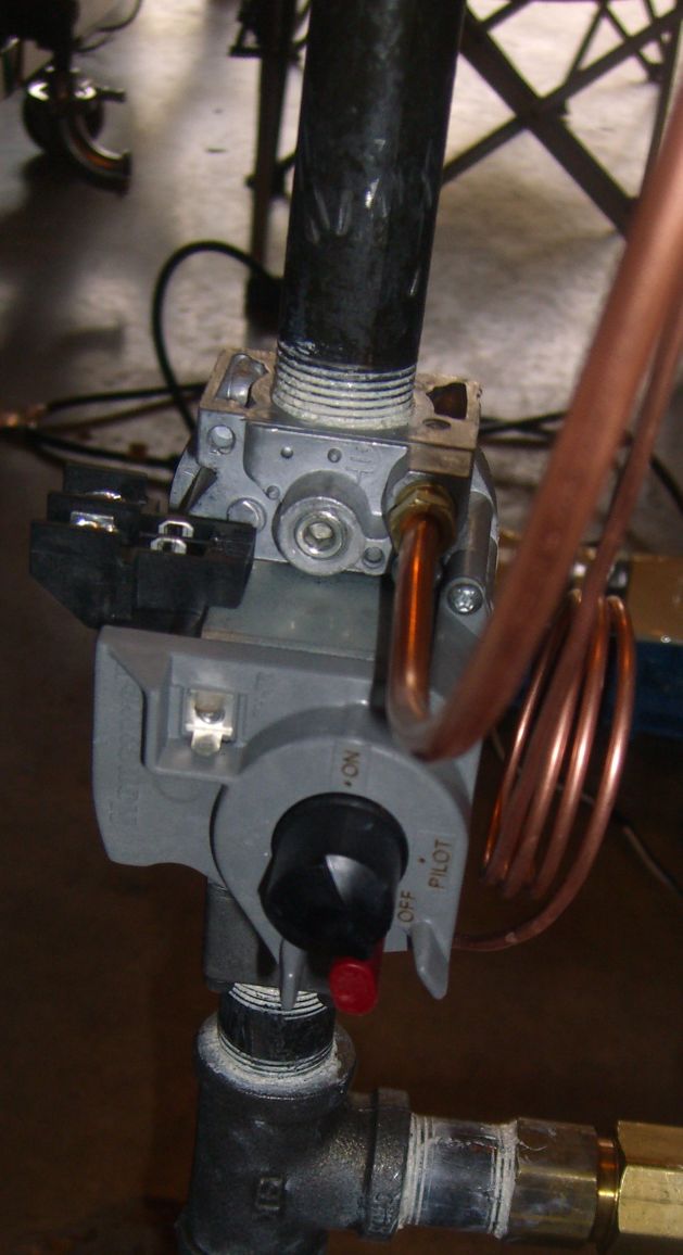
Such conflicts may not have ultimately existed, but my concern was enough that I went ahead and opted for the Honeywell VR8300A4516 (Continuous Pilot Gas Valve, 24 Vac Dual Standing 3/4" x 3/4" Inlet/Outlet) (Supplier Link) (Honeywell VR8300A manual).  This valve works together with a pilot burner and thermocouple and will close if the thermocouple stops signalling that the pilot is lit. You can also use either propane or natural gas with this valve (requires swapping out a couple of small parts which are included with the VR8300A4516).  I chose the Honeywell Q314A4586 Pilot Burner for Natural or LP Gas (Supplier Link) (Honeywell Manual for Q314 Pilot Burners) (Honeywell Product Data for Q314 Pilot Burners) to couple with the gas valve.


Compared to the direct spark ignition models, the continuous pilot/thermocouple valves require a little more effort at the beginning of the brew day (it takes a few minutes to light each pilot), but they are equally safe (close enough for me anyway) and much less complicated.  These valves are surprisingly large, so be sure you plan for the space that'll be required underneath your kettles for the valve, piping, thermocouple and pilot gas tubing.  Also keep in mind the swing radius that would be required if you find yourself needing to thread the valve onto a pipe as opposed to threading a pipe into the valve.

Tuesday, December 21, 2010

March 815-SS-C pumps

The pumps I chose for the Bluto 555 are the 815-SS-C hydronic pumps by March.  March is popular among homebrewers, and I was happy to find a model that seems to work very well on this system.  The 815-SS-C's pump housing is stainless steel, and the pump is supposed to be able to achieve a flow rate of 8 gallons per minute.  The rate you actually get will depend on a variety of factors, including headspace, the tubing used and the use of various tees and elbows.

In my tests so far moving water from one kettle to another, I've consistently observed a rate of just over 6 gpm.  Assuming a mash with 100 lbs of grain and a liquor/grist ratio of 1.25 quarts/lb. (31.25 gal), the pump should facilitate a 5 minute dough in, which is plenty fast.  For RIMS wort return and sparge rate, I'll rely on the return port butterfly valve's incremental positions to restrict the flow to a slower rate.

manual
dimensional drawing
performance curve

electrical system diagram

This would never have gotten done without the help of Adam at ECC.  (click here for the full .pdf file)  The first page shows the layout of the Main Enclosure front panel, where the lights, switches and buttons are.  The second page is the back panel layout, showing where all the SSRs, terminal blocks, BSC-462, etc. will be located.  Pages 3, 4 and 5 are wiring details for inside the Main Enclosure, and pages 6 and 7 are wiring details for the five Satellite Enclosures.

Click image for full 7 page .pdf file

Monday, December 20, 2010

process control components for each kettle

I'd like to be able to brew any beer style, using any brewing technique. I could've stuck with a 3 vessel system and brewed a single barrel at a time of many different beer styles, but as I explained earlier, I wanted to be able to brew a second 1bbl batch simultaneously, and even dump the spent grains from those and start third and forth beers while the first two boiled. And I also started thinking what if I want to do a turbid or decoction mash requiring a fourth vessel. The more I thought about this system, the more I realized how versatile it could be if each of the five kettles were configured to be able to perform any of the brewing functions that might be performed. I'm sure there's something I'll be able to do with the system that I haven't considered yet.

I had five different process control components (ie, inputs, on/off devices) in mind, so I designed the system so that each of the five kettles has the following five control components available to it to control what's happening in the brew session:
  • temperature probe
  • a pump
  • an electronically controlled gas valve
  • a float switch
  • a solenoid valve for liquid
The solenoid valves will get the least use as far as I anticipate, but as the electrical system was being designed, it was decided to go ahead and plan for them.  All the components are unpluggable at NEMA 4x rated enclosures beneath each kettle (I call them satellite enclosures), and these satellite enclosures are all wired to a Main Enclosure on one side of the system.

Sunday, December 19, 2010

more on Bluto 555 Processes

From the ECC wiki concerning state machines:
The BCS controller uses the concept of "State Machines" to program control sequences. State Machines are simply a way to abstract control rules into something that the controller can process. ... The BCS-460 allows up to eight active Processes, each process with up to eight States, and each state up to four Exit Conditions. Exit conditions can be triggered by a temperature reading, a timer value, a user input, or a discrete input (switch). Outputs can be asserted directly in a State (On/Off), by variable duty cycle, or they can be controlled Differentially or by PID control. Each state can assert any or all of outputs uniquely. In addition to allowing Processes control Outputs automatically, users are also able to control the Outputs manually via the web interface.
Here are the state machine processes to be used by the Bluto 555:

The HLT process (Process 0 below) is used to cycle through the main tasks of the HLT, namely fill, fill/heat, and heat.  The user can cycle through these states by either pressing the "Process Continue" button on the panel, or by using a web user input button (WIN) on the BCS interface.  The user can also jump to/from any state with the "Jump State" button in the BCS interface.

click to enlarge
The Kettle X process (Process 1 below) can be used for each kettle, 1-5. It allows the kettle to function in one of four modes, Mash, Sparge, Boil or Chill. This is the process that could be used for all Brewday Options (single barrel, double barrel, consecutive double barrel, extended).

click to enlarge

the Tippy Dump Mechanism

Since I began brewing, I've always called a mash tun that can tilt over on a pivot in-place for easy cleaning a tippy dump.  I think I read it somewhere on a homebrew message board years ago and it just stuck.  I'm sure the first tippy dump I ever saw was on the B3 website (and Michael Fairbrother's webpage) and, like almost every other serious homebrewers, I drooled over those systems.  B3 actually calls their system the Tippy BrewSculpture and has this to say about it:

The Tippy BrewSculpture is by far our best selling design, and for good reason. It features a mash tun that is in a tippy basket that can be locked in position and then tipped over for ease removal of your grains after mashing.
If you've brewed many all-grain batches, you can easily imagine how nice it would be to be able to tump your mash tun over in place and lock it in a position that makes the kettle easy to empty and clean.  I had to have it for this system, and though it ended up being a bit of a problem and adding significantly to the cost, I'm sure it'll end up saving my back.

All 5 of the kettles are in a tippy dump harness, and each will lock in place with a pin in both the upright position and in the tilted, horizontal position.  No doubt, the tippy dump harnesses were the most challenging part of the frame build.


More pics of the tippy dump are in the Frame Build Phase 1 gallery.

phase 1 of the frame build

Here's what Lonnie Mac wrote in the introduction to Build Brutus Ten for BYO magazine about his experience welding together the frame of the Brutus Ten:
I built Brutus on my living room carpet and my small 6'x8' apartment patio.  The raw stainless steel alone stretched across the threshold, from the dining room to the patio door.  I hooked up a 220-volt welder to the dryer outlet.  During the daytime, no one knew that, beneath the blinding flashes illuminating the whole complex, lay the birth and free-will-victory that is now Brutus Ten.
He bought a small welding system and spent alot of time studying books and message boards and making practice cuts.  In his Build article, he talks about the great pleasure it gave him to learn this new craft.

Having spent 16 years with my nose buried in thousands of pages of statutes and regulations, I can totally understand the excitement that comes with stretching your mind in a new direction.  Brewing has always done that for me.  But, I have to admit that if I'd tried to cut and weld the Bluto 555 frame myself, the scene would've been more like Paul Timberman's Workshop, with the addition of third degree burns, electrocutions and blindness!!!

So back in August or so of 2009, I started talking to my good friend Rob, who was one of the original members of the Auburn Brew Club back when I started the club in 2007.  He had watched me brew in my basement about a dozen times while putting together his own homebrewing system and learning to brew.  Rob works as a mechanical engineer for a local machine/welding/fabrication company and, because of his knowledge of the brewing process, we were able to communicate really well about what I'd need and the reasons why.


click for more pictures
Rob and I decided to build the frame in 2 phases: the first being the basic frame and the "tippy dump" harnesses.  (Click here for more pics of Phase 1 of the frame build).  Once we got that done, I brought it home to further contemplate the design for the additions of the attachment points for the electrical and gas plumbing components, which would be phase 2 of the frame build.  There are 8 casters, and I believe they're rated to 600lbs each, so I shouldn't have any problems with them, even if all 5 kettles were completely full at the same time.  The frame is about 12 feet long and 2 feet wide, and it's a little over 5 feet from the floor to the top of the kettles.

the 55g Blichmann Boilermaker kettles

I got the Blichmann Engineering kettles back in September or so of 2009, and I was so happy to be getting started on the project.  Blichmann is very well known in the homebrewing community and has been making products suitable for small brewpubs and nanobreweries for quite a while.  My sensei Todd (the student has now become the masta) couldn't resist getting inside one.  And I couldn't resist modifying the kettles, so at some point I'll post some pics of them with a couple extra holes in each and sanitary butt weld ferules for tri-clamp fittings welded on.


According to Blichmann's Boilermaker page, one of these 55g kettles will hold between 75 and 135 lbs of grain for a mash, depending on your chosen liquor to grist ratio, will recirculate at up to 2.25 gpm and has a recommended lauter rate of .5 gpm.  I can't wait to put 'em through some tests to confirm!

the BCS-462 Brewery Control System

I'm trying to retrace 18 months of planning and building over the next couple of months, and before I get too far, I need to make a post about the "brains" of the Bluto 555 system, and that is the BCS-462 Brewery Control System, made by Embedded Control Concepts.  From the ECC site:
Originally designed as an interactive temperature controller for small to medium size breweries, the BCS series controllers have gained wide popularity with homebrewing, winemaking, and mead making applications.  It is also used as a general purpose industrial controller due to its inherent flexibility.  The BCS monitors temperature sensors and discrete inputs (switches), and controls outputs (relays) which in turn open or close valves, switch heating elements, or control other devices.  The BCS connects to your network, and all interfacing with the controller is done through a web browser allowing all process information to be displayed in a simple, easy to read and intuitive format.  The virtual control panel is packed full of information, and is much more cost effective than panel mount touchscreens coupled with a multitude of wired switches and lights. ... You can create sequences to hold temperatures for adjustable times, and react to external inputs.  The BCS is programmed using intuitive rules. ... Once it is configured and on the network, users can access it from any device that has an HTML based web browser.  Access the BCS from Windows, Mac, Linux, Android, iPhone, or iPod Touch. ... you can monitor (and control) the BCS remotely.  From anywhere. ... Heat/Cool, PID control, differential control, temperature ramping, mp3 alarms, and PWM outputs are all standard features.  Data is logged internally in the device, and displayed on your browser, or saved as a text file.


There's alot more to show about how the BCS-462 will work on the Bluto 555, but I wanted to go ahead and at least provide a reference.  The ECC website has tons of information about how the controller works for anyone who might be interested, and Adam at ECC has been instrumental in helping me with the automation aspects of the Bluto 555.

Double Barrel Process

Here's a description of the process for brewing two different 1bbl batches (or you could brew 2bbl of the same beer) at the same time.  This will need some debugging and probably revisions, but this is a good first draft to work with.  For some reason, my brain insists on having the process go from R to L, from K5 to K1.  ... probably the result of some brain damage at some point.  The detailed process below each image might look complicated if you're not already really familiar with the BCS-462 controller and how it controls this system, but I've underlined terms to show that all the brewer is doing manually is pressing/clicking buttons, setting float switch heights, opening/closing valves and stirring the mash. The BCS-462 does the rest.  Note that some of the steps' activities are occurring at the same time.

A more detailed version of the steps is below each image, but here's a simplified version of what's happening.
  • 01 - fill up the HLT
  • 02 - begin recirculating and heating the HLT
  • 03 - dough in K4 mash
  • 04 - refill HLT
  • 05 - recirculate K4 mash and step temperatures
  • 06 - dough in K2 mash
  • 07 - refill HLT
  • 08 - recirculate K2 mash and step temperatures
  • 09 - sparge K4
  • 10 - runoff from K4 to K3; boil
  • 11 - sparge K2
  • 12 - runoff from K2 to K1; boil
  • 13 - Whirlpool/Chill K3 wort
  • 14 - Whirlpool/Chill K1 wort
  • 15 - Send K3 wort to Fermentation Vessel
  • 16 - Send K1 wort to Fermentation Vessel

01 - Enable BCS-462's "K5 HLT Sequence" process. Press "Process Continue" button on Main Enclosure (or click Win0 in BCS-462 interface) to enter "K5 HLT Fill" state. BCS-462 controller opens TWH solenoid valve to send 160F water to HLT; Controller closes TWH solenoid valve on K5 float switch signal.

02 - Open valves to prime K5 pump and permit recirculation; Press "Process Continue" button on Main Enclosure (or click Win0 in BCS-462 interface) to fill/heat entering "K5 HLT Fill/Heat" state; BCS-462 turns on K5 pump to begin recirculating HLT water; Controller turns on K5 burner as necessary to raise the water temperature up from 160F to precise strike temperature desired.
03 - After HLT water is at desired temperature, press "Process Pause" button on Main Enclosure (or click Win0 in BCS-462 interface) to stop "K5 HLT Fill/Heat" state; K5 pump remains on; open valves at K5 pump exit and K4 main port; watch K5 sight glass; when Level 1 minus Level 2 equals desired quantity of strike water, close valves and stir mash.
04 - This step can begin anytime after K5 pump exit valve is closed in Step 3; press "Process Continue" button on Main Enclosure (or click Win0 in BCS-462 interface) to fill/heat entering "K5 HLT Fill/Heat" state; BCS-462 controller opens TWH solenoid valve to send 160F water to HLT; Controller closes TWH solenoid valve on K5 float switch signal; Controller turns on K5 burner as necessary to raise the water temperature up from 160F to precise strike temperature desired.
05 - After stirring mash in K4, open valves to prime K4 pump and permit recirculation; Enable BCS-462's "Kettle4" process; click Win0 in BCS-462 interface to start mash steps; Controller turns on K4 pump and K4 burner as necessary to maintain or step up mash temperature; when mash is complete, controller stops K4 pump and K4 burner activity.
06 - After HLT water is at desired temperature, press "Process Pause" button on Main Enclosure (or click Win0 in BCS-462 interface) to stop "K5 HLT Fill/Heat" state; K5 pump remains on; open valves at K5 pump exit and K2 main port; watch K5 sight glass; when Level 1 minus Level 2 equals desired quantity of strike water, close valves and stir mash.
07 - This step can begin anytime after K5 pump exit valve is closed in Step 6; press "Process Continue" button on Main Enclosure (or click Win0 in BCS-462 interface) to fill/heat entering "K5 HLT Fill/Heat" state; BCS-462 controller opens TWH solenoid valve to send 160F water to HLT; Controller closes TWH solenoid valve on K5 float switch signal; Controller turns on K5 burner as necessary to raise the water temperature up from 160F to precise sparge water temperature desired.
08 - After stirring mash in K2, open valves to prime K2 pump and permit recirculation; Enable BCS-462's "Kettle2" process; click Win0 in BCS-462 interface to start mash steps; Controller turns on K2 pump and K2 burner as necessary to maintain or step up mash temperature; when mash is complete, controller stops K2 pump and K2 burner activity.

09 - set float switch on K4 to desired height; open valve at K5 pump exit to send sparge water to K4 return port; open valve to permit wort to exit K4 main port and prime pump; enable "Kettle4" process; click Win1 in BCS-462 interface to start sparge; Controller turns on K4 pump and opens/closes K4 return port solenoid valve as indicated by K4 float switch signals.
10 - open valve at K3 main port (set butterfly valve position to control runoff speed); set float switch on K3 to desired height; enable "Kettle3" process; click Win2 in BCS-462 interface to start preboil; turn on/off K3 burner manually as necessary to ramp up close to boil; Controller turns off K4 pump when K3 float switch signals that desired volume has been reached; close valves; begin boil.
11 - set float switch on K2 to desired height; open valve at K5 pump exit to send sparge water to K2 return port; open valve to permit wort to exit K2 main port and prime pump; enable "Kettle2" process; click Win1 in BCS-462 interface to start sparge; Controller turns on K2 pump and opens/closes K2 return port solenoid valve as indicated by K2 float switch signals.
12 - open valve at K1 main port (set butterfly valve position to control runoff speed); set float switch on K1 to desired height; enable "Kettle1" process; click Win2 in BCS-462 interface to start preboil; turn on/off K1 burner manually as necessary to ramp up close to boil; Controller turns off K2 pump when K1 float switch signals that desired volume has been reached; close valves; begin boil.

13 - At completion of boil, turn off K3 burner; open valves to permit recirculation from K3 main port to K3 return port; enable "Kettle3" process; click Win3 in BCS-462 interface to start Chill/Whirlpool process; Controller turns on K3 pump to begin wort recirculation whirlpool; Controller opens K3 chiller inlet solenoid valve to allow cold water into chiller coil; when desired temp is reached, process is automatically disabled, turning off valve/pump; allow wort to settle.

14 - At completion of boil, turn off K1 burner; open valves to permit recirculation from K1 main port to K1 return port; enable "Kettle1" process; click Win3 in BCS-462 interface to start Chill/Whirlpool process; Controller turns on K1 pump to begin wort recirculation whirlpool; Controller opens K1 chiller inlet solenoid valve to allow cold water into chiller coil; when desired temp is reached, process is automatically disabled, turning off valve/pump; allow wort to settle.

15 - Turn on K3 pump to send wort to fermenter; turn off K3 pump when complete.

16 - Turn on K1 pump to send wort to fermenter; turn off K1 pump when complete.